Assignment 4: Libraries
Touch spoon, motor spin: quite simply, the Peak of Modern Technology™.
February 13, 2021
This assignment wanted us to become familiar with using Arduino libraries and non-standard functions, objects, and syntax. I originally really wanted to use the joystick component, but apparently that's just two potentiometers and doesn't need an external library to run (drats!). I settled instead to work with capacitive touch and the servo motor I had.
The plan was simple: make input from the capacitive sensor spin the motor at a proportional rate. This time, I wanted to start with the code, as I am now familiar enough with the language to not have to compile, run, and debug every line of code.
Code for the Capacitive Sensor and the Servo Motor
The code for this was actually pretty simple, as I had many of the parts made from in-class activity. My capacitive sensor needed time to calibrate, and I have learned how to calibrate since last assignment (yay learning). I added a phase during setup that would pull max and min values from the environment. I also had the basics of the motor down, as it wasn't that much line of code. The program reads a value from the spoon, maps it to a range of 0–180 degrees, then moves the servo by that value. I also have the readings printed to the serial monitor for debugging.
/*
* Ben Olson
* 02/13/21
* This program calibrates and reads a capacitive sensor, then maps read values
* to a range of 0–180 degrees. These values are outputted to a servo motor,
* which moves by that number of degrees. The sensor values are also printed
* to the serial monitor.
*/

#include <CapacitiveSensor.h>
#include <Servo.h>

// constants
CapacitiveSensor cs_4_2 = CapacitiveSensor(4,2);     // 1 MΩ resistor between pins 4 and 2 for
                                                    // absolute touch to activate,
                                                    // pin 2 is sensor pin

Servo myServo;                                       // creates a servo object
const int OUTPUT_PIN = 9;                            // output of capacitive sensor
const int LED_PIN = 7;                               // pin that controls LED
const int calliLength = 5000;                        // length of calibration period

// variables
long sensorValue = 0;     // the sensor reading value
long sensorMin = 30000;   // the min sensor value
long sensorMax = 0;       // the max sensor value

void setup() {
 // turn off autocalibrate on channel 1
 cs_4_2.set_CS_AutocaL_Millis(0xFFFFFFFF);

 // inits serial monitor at band 9600
 Serial.begin(9600);

 // inits LED and output pins to output
 pinMode(OUTPUT_PIN, OUTPUT);
 pinMode(LED_PIN, OUTPUT);

 // attaches the servo on output pin to the servo object
 myServo.attach(OUTPUT_PIN);

 // signals the start of the calibration
 digitalWrite(LED_PIN, HIGH);

 // while timer is less than calibration period
 while (millis() < calliLength) {
   sensorValue = cs_4_2.capacitiveSensor(30);
   Serial.println(sensorValue);

   // sets max sensor value to the higher value between current reading and max
   if (sensorValue > sensorMax) {
     sensorMax = sensorValue;
   }

   // sets min sensor value to the lower value between current reading and min
   if (sensorValue < sensorMin) {
     sensorMin = sensorValue;
   }


   delay(20);
 }

 // signals the end of the calibration
 digitalWrite(LED_PIN, LOW);

}

void loop() {
 sensorValue = cs_4_2.capacitiveSensor(30);

 // maps the sensor input values to degrees
 sensorValue = map(sensorValue, sensorMin, sensorMax, 0, 180);

 // constrains reading to strict degree range
 sensorValue = constrain(sensorValue, 0, 180);

 // writes sensor value as analog degree to servo
 analogWrite(OUTPUT_PIN, sensorValue);


 // prints the sensor range and the current sensor reading to the serial monitor
 Serial.print("min value: ");
 Serial.print(sensorMin);
 Serial.print(" < ");
 Serial.print(sensorValue);
 Serial.print(" < max value: ");
 Serial.println(sensorMax);

 // if the sensor is reading a value greater than 0
 if (sensorValue > 0) {
   myServo.write(sensorValue); // writes servo to angle mapped from sensor
   delay(500);                 // only delays if it reads a value
 }

 delay(100); // delays by 100ms to try and minimize spikes in read values

}
Wiring the Circuit
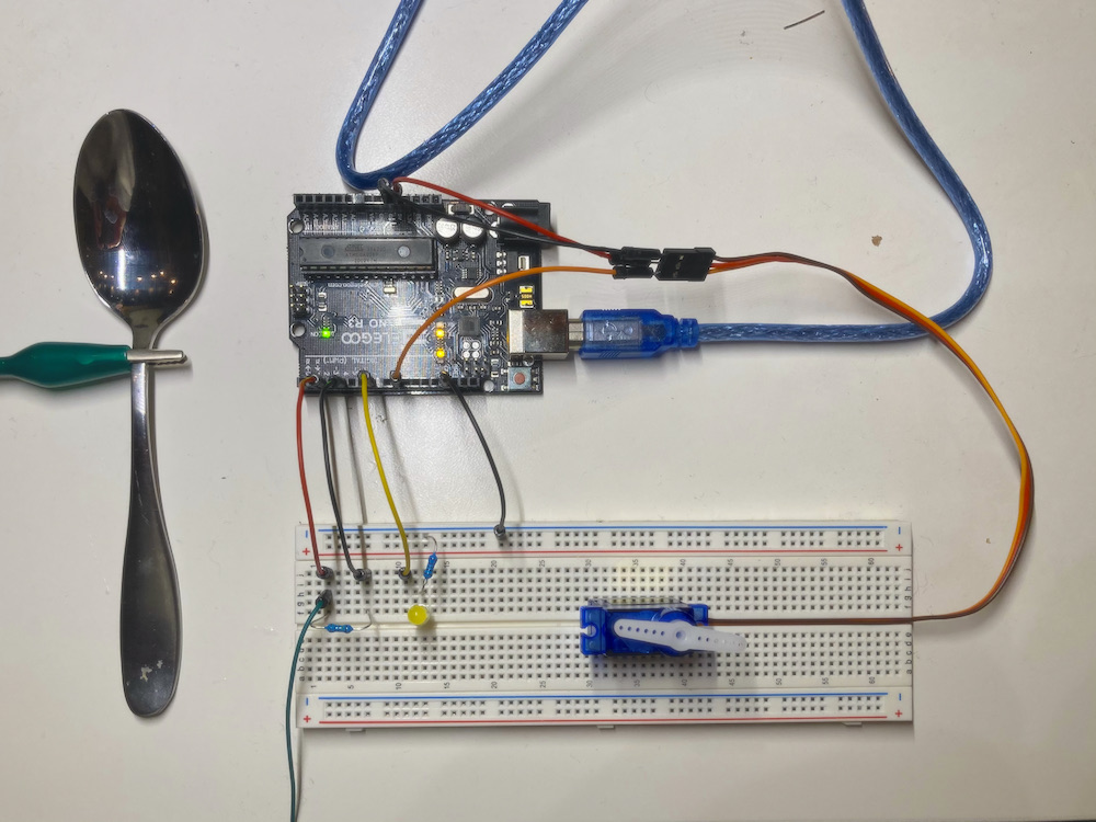
Wiring circuits has become a lot easier than the first assignment. At this point, I knew that the best method for my success is to chunk out the code to make sure one function works at a time. I started with making sure my spoon was feeding input data, then I tested calibration, then added a calibration indicator via LED before finally adding the servo. Chunking it out this way helped me write code and debug without having to backtrack all the way to step 1 if something went wrong.
For resistances, the capacitive sensor needed a 1MΩ resistor in order for it to read absolute touch. For the yellow LED, the voltage drop of 1.8V...yeah basically I need a 220Ω resistor; if you can't take my word for it, go back to Assignment 2 for my rationale.
Making the Schematic
The schematic was my last step. This was also easy and not as time-consuming; I had been getting pretty familiar with circuit-diagram.org, the software I use to draw my schematics.
Touch spoon...motor spin?
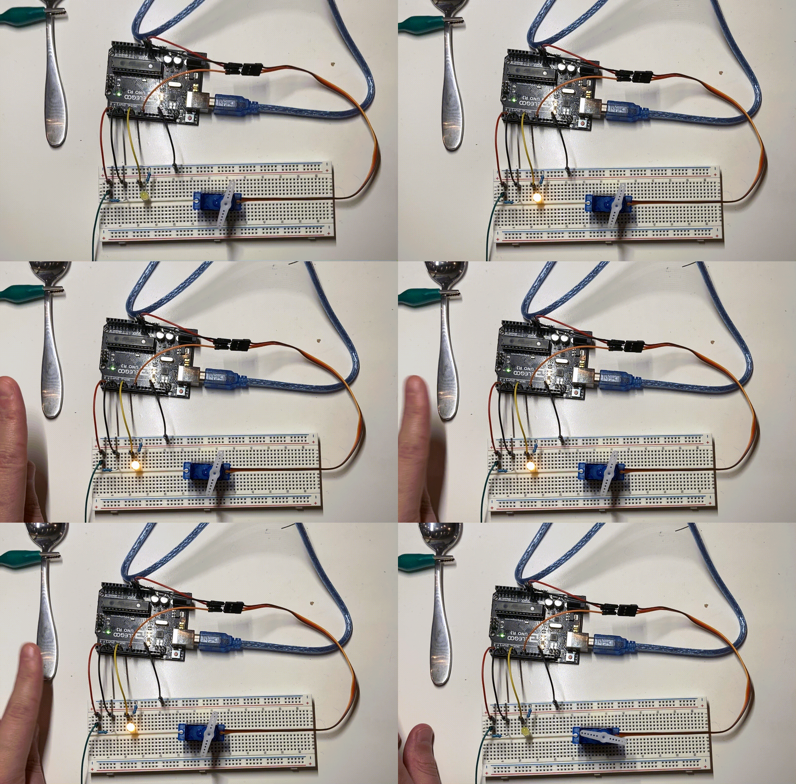
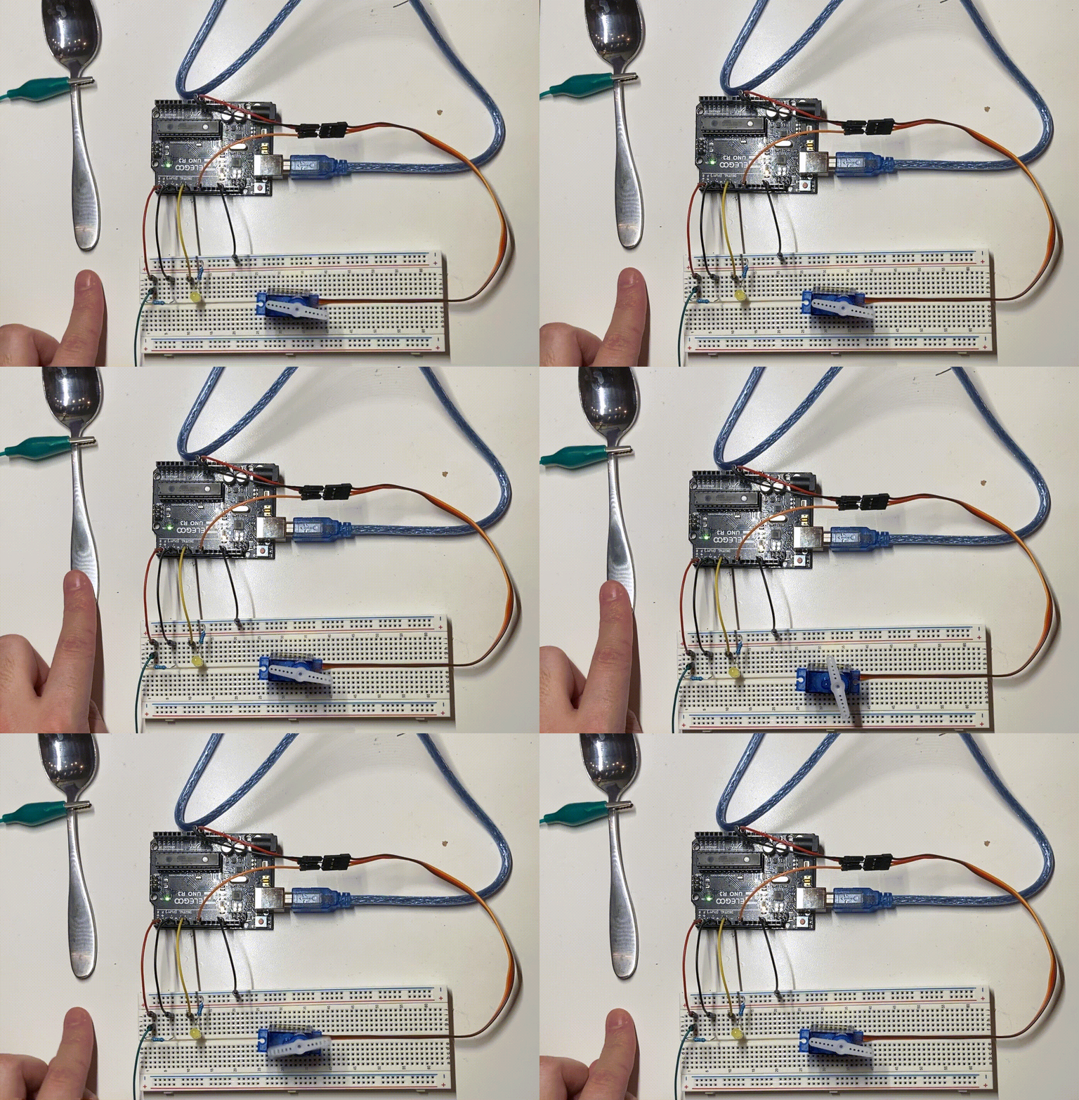
After everything was done, I uploaded the program and calibrated the sensor by repeatedly tapping the spoon.

Then, I waited, and then tapped my finger on the spoon, and...surprise, surprise! It worked.

This assignment felt really good to complete. I never once had a hiccup or moment of confusion, and I managed to complete all of the parts in half of the time. I can finally put away my circuit box for the weekend and clean my desk space!