Assignment 5: High(er) Voltages and Transistors
Feel* the sensation of a cool, summer breeze..
*Must be one inch away from the fan.
February 20, 2021
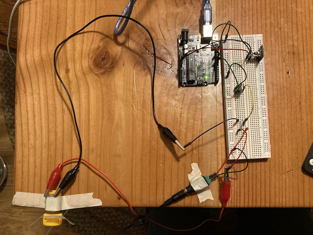
This assignment called for us to use a transistor to manipulate voltage. I wanted to make a remote-controlled fan, which required an IR setup and the DC motor. I was really excited to play around with my brand new, shiny IR receiver, and got to work immediately setting up the code.
Code for the IR Receiver and Fan Motor
The code was confusing at first, as it required me to digest and understand the IR Receiver library that I used. The example setup helped me gain a rudimentary understanding of the idea here, and that was good enough for the purposes of my circuit.
/*
* Ben Olson
* 02/20/21
*
* This program allows users to remotely control the torque of the motor using an IR receiver and remote.
* The code initializes the IR reciever and watches for input. The code configures a power level, which is controlled by the remote's
* numerical inputs and the up and down buttons. This value is constrained, mapped. and outputted to the motor.
*
* Some of the following code for the IR Receiver was taken by Armin Joachimsmeyer from SimpleReceiver.cpp.
* Source: https://github.com/Arduino-IRremote/Arduino-IRremote/blob/master/examples/SimpleReceiver/SimpleReceiver.ino
*
*/

/*
* Specify which protocol(s) should be used for decoding.
* If no protocol is defined, all protocols are active.
*/
#define DECODE_NEC 1

#include <IRremote.h> // includes IR receiver library


// initalizes constants
const int IR_RECEIVE_PIN = 11;  // pin that receives IR input
const int FAN_PIN = 9;          // pin that outputs signal to fan gate

// intializes variables
int powerLevel = 0;   // indicates power level, value range 0-9
int fanSpeed = 0;     // controls the mapped fan speed, value range 0-255

void setup() {

   // sets fan pin to our put
   pinMode(FAN_PIN, OUTPUT);

   // initializes serial monitor
   Serial.begin(115200);

   // just to know which program is running on my Arduino (taken from SimpleReceiver)
   Serial.println(F("START " __FILE__ " from " __DATE__ "\r\nUsing library version " VERSION_IRREMOTE));

   /*
    * Start the receiver, enable feedback LED and take LED feedback pin from the internal boards definition (from SimpleReceiver)
    */
   IrReceiver.begin(IR_RECEIVE_PIN, ENABLE_LED_FEEDBACK);

   // prints that the program is ready to receive input
   Serial.print(F("Ready to receive IR signals at pin "));
   Serial.println(IR_RECEIVE_PIN);
}

void loop() {
   /*
    * Check if received data is available and if yes, try to decode it.
    * Decoded result is in the IrReceiver.decodedIRData structure.
    *
    * E.g. command is in IrReceiver.decodedIRData.command
    * address is in command is in IrReceiver.decodedIRData.address
    * and up to 32 bit raw data in IrReceiver.decodedIRData.decodedRawData
    *
    * Taken from SimpleReceiver
    */
   if (IrReceiver.decode()) {

       /*
        * !!!Important!!! Enable receiving of the next value,
        * since receiving has stopped after the end of the current received data packet.
        *
        * Taken from SimpleReceiver
        */
       IrReceiver.resume(); // Enable receiving of the next value

       /*
        * Checks input value from IR Receiver; if it matches a case, assigns power level according to the type of input
        */
       switch (IrReceiver.decodedIRData.command) {
         // the two following cases track the 'up' and 'down' buttons on the remote, adds 1 unit to power level
         case 0x09: powerLevel++;
            break;
         case 0x07: powerLevel--;
            break;
         // cases hereafter map the numerical input value to the power level
         case 0x16: powerLevel = 0;
            break;
         case 0x0C: powerLevel = 1;
            break;
         case 0x18: powerLevel = 2;
            break;
         case 0x5E: powerLevel = 3;
            break;
         case 0x08: powerLevel = 4;
            break;
         case 0x1C: powerLevel = 5;
            break;
         case 0x5A: powerLevel = 6;
            break;
         case 0x42: powerLevel = 7;
            break;
         case 0x52: powerLevel = 8;
            break;
         case 0x4A: powerLevel = 9;
            break;
         // if button doesn't match, prints error
         default: Serial.println("Unsupported Command");
            break;
       }

       // constrains power level to range of 0-9
       powerLevel = constrain(powerLevel, 0, 9);

       // prints power level to serial monitor
       Serial.print("Fan Power Level: ");
       Serial.println(powerLevel);

       // maps power level from 0-9 to 0-255, the analog range for fan pin
       fanSpeed = map(powerLevel, 0, 9, 0, 255);

       // assigns motor the aforementioned analog speed
       analogWrite(FAN_PIN, fanSpeed);

   }
}
Most of the code is to set up and watch the IR remote for active input. The last few lines of the code take in the value gathered from the remote, then assign it, constrain it, map it, then output it to the motor.
Making the Circuit Schematic
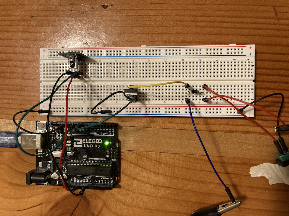
The circuit schematic was pretty straightforward; the IR receiver sends a signal to pin 11, and the motor is wired using a transistor and flyback diode setup that we learned from class. There are no resistors in this circuit; honestly, this kind of made my day, as I didn't have to go and figure out what resistances I needed. I could be completely wrong and need a resistor in some fashion, but from the class examples and my knowledge of the IR receiver and fan motor, this seemed to be okay.
Crossing my fingers that my table doesn't light on fire
Acknowledgements of High Voltage
My IR receiver was independently connected to 5V from the Arduino, and hooked to an independent ground. This prevented any potential noise from the motor circuit from interfering with the IR receiver capabilities.
My motor and transistor were connected to a 9V battery, which meant that was the maximum my motor circuit would see. I'm not sure why in the examples I don't see a resistor; is it because the transistor does something special? Or does the motor circuit not need a resistor in order for current to be calculated? In any case, the current to me is unknown: probably a no-no. However, there does appear to be some resistance, otherwise there'd be no current. I'm not quite sure what to make of it. Regardless, the circuit seemed to get a stamp of approval, so with the flyback diode I was good to go. The flyback diode prevents any current created on power down from traveling back upstream.

After putting off building the circuit, it was time. I was really nervous about wiring everything together; the fact that my last IR receiver did not go over super well made me apprehensive about hot-wiring. I made sure that all components were situated and double checked everything was in order before plugging it in. After bracing for metaphorical (and possibly physical) impact, I plugged in the battery and...

It worked! Just kidding; this was acutally after hours of troubleshooting. The problem was that the IR receiver would respond to the first input, and then freak out and not respond to any remote input. At first, I thought it was my code, then I thought it was my motor setup, or that there wasn't any resistor to limit current.
In an act of desperation, I moved my IR receiver ground wire from the general ground line I had my other components attach to to an independent ground. For some reason, this did the trick. I have no idea why sharing ground would interfere with the IR receiver, but one thing I know for sure; sometimes, don't question the good things in life.