Assignment 2: Fade
Things to push, twist, rotate, wave your hand over, stick in the freezer!
January 24, 2021
The fade assignment tests us students on our abilities to manipulate voltage and pin output using voltage dividers and some fancy Arduino code. I didn't have much of a plan going into this one like last time, but I knew that I wanted to use the RGB LED to make some sort of rainbow effect. Let's see how this went:
Starting with the Schematic this time
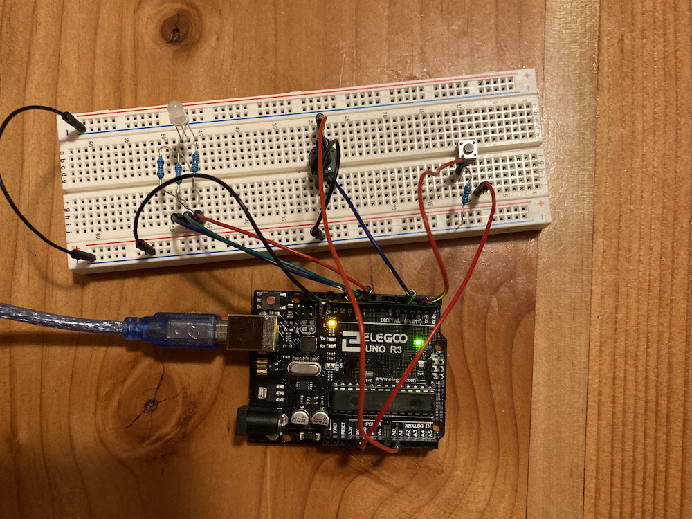
Unlike the previous assignment, I had no preset circuit on my board to easily tinker with. Instead, I decided to chunk the parts down one at a time. I knew that I was going to incorporate the potentiometer as well as the button.
Instead of connecting the three components in series, I wanted to reroute the power from the button into the Arduino, then output it to the potentiometer (same with the potentiometer and the three independent LED connections). This was so we could manipulate the signal with code.
I also wanted to see what the schematic looked liked when it was connected with the Arduino microcontroller. This was more confusing to read because of the circuits crossing and the fact that wiring ground looks weird, but here it is anyways! (Probably will stick to the previous method in future assignments.)
Calculating Resistance
The resistors were solved using the DC current of the LEDs, which is 30mA, and the voltage drop of each color. Red and green are the same, with a voltage drop of 1.8V each. Therefore, figuring out ideal resistance is as simple as plugging in values in Ohm's Law (from a 5V input). V = I*R, so R = 160Ω. We always want to be equal to or greater than the ideal resistance, so I picked the 220Ω resistors for red and green. Blue differs with a voltage drop of 3.3V drop. That value gives me an ideal 85Ω, so I used a 100Ω resistor for the blue LED in series.
Coding the Button and Potentiometer
Now had to code the button and potentiometer. I wanted the button to toggle with a debounce delay, so I used the Arduino IDE's Debouce example and configured it to my pins.
I wanted the button to toggle the potentiometer, so that became my output for pin 4. The potentiometer was then going to go to pin A0, where it could analog read the variable voltage. The varying voltage was assigned to a maxValue variable; this variable controlled the maximum luminosity of the LED loop.
The LED for loop
The LED loop itself was something I made during the 2nd week of class. It is a series of for loops that cycles through which LED of the RGB LED is receiving power while the other two are drained of it. This results is a pattern that constantly shifts colors.
/*
*  This program codes a toggleable button that controls the power supply of a potentiometer.
*  The potentiometer controls the voltage of an RGB LED, which is set to rotate through colors
*  in a series of for loops.
*
*  Code used:
*  Debounce by Davit A. Mellis (2006), last modified by Arturo Guadalupi (2016)
*  http://www.arduino.cc/en/Tutorial/Debounce
*/


// initalize button and potentiometer pins
const int buttonInPin = 2;  // the number of the input pushbutton pin
const int buttonOutPin = 4; // the number of the output pushbutton pin
const int analogInPin = A0; // the number of the analog input pin

// initailize the RGB LED pins
const int redPin = 9;       // the number of the red light on the RGB LED pin
const int greenPin = 10;    // the number of the green light on the RGB LED pin
const int bluePin = 11;     // the number of the blue light on the RGB LED pin

int ledState = LOW;         // the current state of the output pin
int buttonState;             // the current reading from the input pin
int lastButtonState = LOW;   // the previous reading from the input pin
int sensorValue = 0;         // value read from the pot
int maxValue = 255;          // value computed after sensor value mapping


unsigned long lastDebounceTime = 0;  // stores the last instance of state change
unsigned long debounceDelay = 100;    // the debounce time

void setup() {
 // Initializes the pins to output or input
 pinMode(buttonInPin, INPUT);
 pinMode(redPin, OUTPUT);
 pinMode(greenPin, OUTPUT);
 pinMode(bluePin, OUTPUT);
 pinMode(buttonOutPin, OUTPUT);

 // Sets the initial LED state
 digitalWrite(buttonOutPin, ledState);
}

void loop() {
 /*
  * Code taken from Debounce. Allows the push button to have a toggle state
  */
 // reads the state of the button and assigns into a local variable:
 int reading = digitalRead(buttonInPin);

 // checks if the button state changed due to noise or pressing:
 if (reading != lastButtonState) {
   // reset the debouncing timer
   lastDebounceTime = millis();
 }

 // checks if the reading has been there longer than the debounce delay
 if ((millis() - lastDebounceTime) > debounceDelay) {

   // checks if buton state changes
   if (reading != buttonState) {
     buttonState = reading;

     // toggles the LED if the new button state is HIGH
     if (buttonState == HIGH) {
       ledState = !ledState;
     }
   }
 }


 // writes HIGH to the button's output pin:
 digitalWrite(buttonOutPin, ledState);

 // saves the current reading to be referred in the next loop
 lastButtonState = reading;

 /*
  * End code taken from Debounce.
  */

 // read the potentiometer value:
 sensorValue = analogRead(analogInPin);

 // map it to the luminosity range:
 maxValue = map(sensorValue, 0, 1023, 0, 255);

 // loops up to max value, writing analog value to red pin and decreasing blue pin
 for (int i = 0; i < maxValue+1; i++) {
   analogWrite(redPin, i);             // increases value of red
   analogWrite(bluePin, maxValue-i);   // decreases value of blue
   delay(5);                           // slight delay in calls
 }

 // adds green, decreases red
 for (int i = 0; i < maxValue+1; i++) {
   analogWrite(greenPin, i);
   analogWrite(redPin, maxValue-i);
   delay(5);
 }

 // adds blue, decreases green
 for (int i = 0; i < maxValue+1; i++) {
   analogWrite(bluePin, i);
   analogWrite(greenPin, maxValue-i);
   delay(5);
 }
}
Final Test
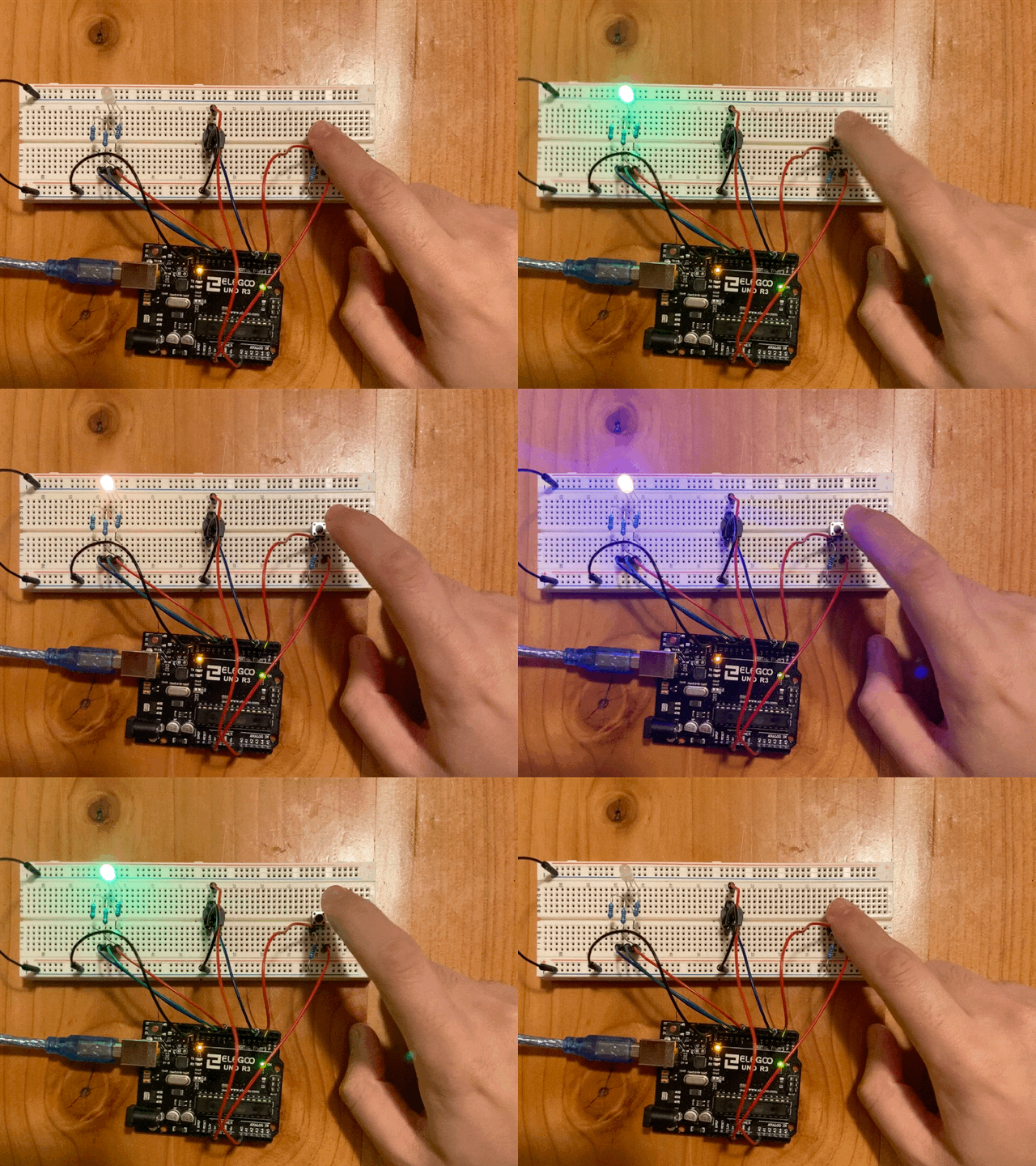
After all of that work, it was time to see if the program actually worked. After loading it successfully onto my Arduino, and...

It worked!! Well, I actually already knew the button worked. I had to ensure that the button and potentiometer were giving variable voltage to a standard LED before I tried manipulating the signal with code.
One effect that I had not anticiapted was the manipulation of speed. This makes sense; as we're decreases the available voltage, the maxValue reads a lower value, making each for loop go through with fewer iterations. The result is a controllable rate for the rainbow animation.
Overall, I'm happy with my result. It took me a while to figure out how to configure the button and potentiometer, but once we got that down, it was smooth sailing!