Assignment 3: Input Output
"If that was you on the phone, and you on the bus…then who was flickering the lights?"
January 31, 2021
This assignment had manipuate the voltage using a voltage divider setup. In this case, we were to use a variable resistor to spice things up, so I chose the photoresistor, as it is one of the easier ones to manipulate in real time. (I would have liked to mess around with an infared receiver, but alas, mine in the kit was most likely faulty.)
My end goal for this circuit was to make the output LED signal dim as the photoresistor received more light. This would (hopefully) make a cool reactive effect to an increased light source.
The Schematic Setup (and Resistance Calculations)
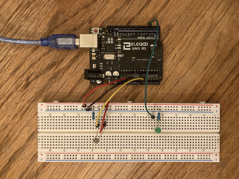
The schematic for this one involved two separate circuits. The first one was a voltage divider, with one of the resistors being the photoresistor and the other a 10kΩ resistor. A resistor is needed to allow the microcontroller to measure a current (otherwise V = I*0), and the resistance dictates the flow of current. It's convention is to use a larger resistance value (~1-10k), as this will reduce the amount of current necessary, so I stuck with 10k.
The voltage out depends on the range of values for R1 in the formula for measuring output voltage: Vout = R2/(R1 + R2)*Vin. My LDR was reading a resistance range of 10k-22.5kΩ. Meaning that a fixed 10kΩ resistor for R2 would give me a min. of 2.5V and a max. of 3.46V. This window of resistance was fine by me, as I could always tweak the map values in the code to accommodate.
The resistance needed for the LED has already been calculated in the previous writeup, but it needs a stable current under 30mA, so a 220Ω resistor will help shoot that target.
Setting Up the Code
The code was simple enough to configure. I set up the pins and assigned varaibles to read the values from the voltage divider. Then, I mapped them to an analog range and constrained the endpoints. The main interesting point is that I took the inverse of the read value; this made it so that a high light value would be outputted as a low LED luminosity.
/*
* Ben Olson
* 01/31/21
* This program reads a photoresistor and outputs inverse values to an LED.
* That is, bright light will cause the LED to dim, whereas it will shine brightest in the dark.
* The program writes the input and output values to the serial monitor.
*/

const int photoIn = A0;   // input pin for photoresistor
const int photoOut = 3;   // output pin for photoresistor
const int minValue = 500; // min value for output brightness. lower value = less sensitive to dark
const int maxValue = 800; // max value for output brightness. high value = less sensitive to light. max value = 1023

void setup() {
 // initializes the output pin
 pinMode(photoOut, OUTPUT);
 // initializes the serial monitor to signal 9600
 Serial.begin(9600);
}

void loop() {
 // reads the analog value from the photoresistor input in
 int input = analogRead(photoIn);
 // constrains the input value to the pre-defined min and max values
 input = constrain(input, minValue, maxValue);
 // maps the input value to the output value (range of analog values)
 int output = map(input, minValue, maxValue, 0, 255);

 // reverses the output value so that it outputs low values with high readings
 output = 255 - output;

 // writes the analog output value to the output pin
 analogWrite(photoOut, output);

 // prints the input and output values to the serial monitor
 Serial.print("input = ");
 Serial.print(input);
 Serial.print("\t output = ");
 Serial.println(output);
}
Putting My Math to the Test
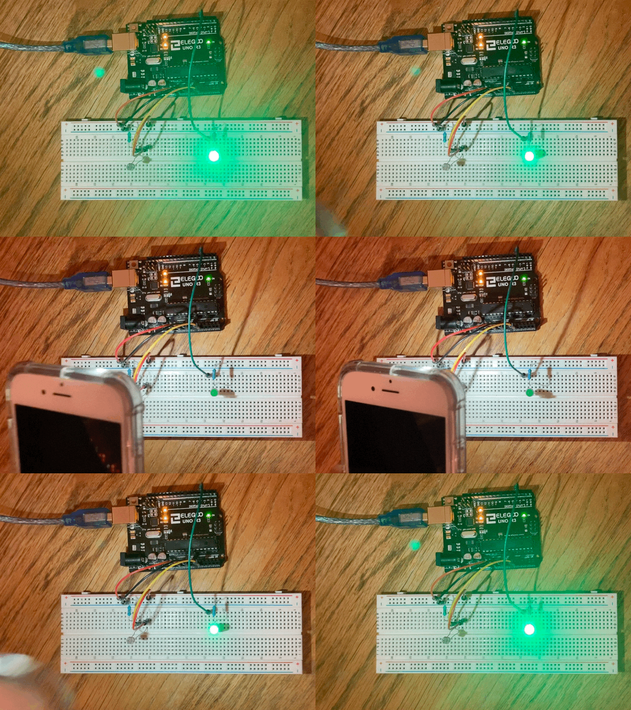
After calculating the resistances and setting up the circuit, I managed to get things working! See my result below:

After some testing, I also managed to tweak the min. and max. map values to make the range sensitive to my light conditions. In the future, I want to try and learn how to callibrate this circuit to automatically configure any light conditions.