Final Project: Party Mode
Party rockers in the house tonight! Everybody just have a good time!
March 10, 2021
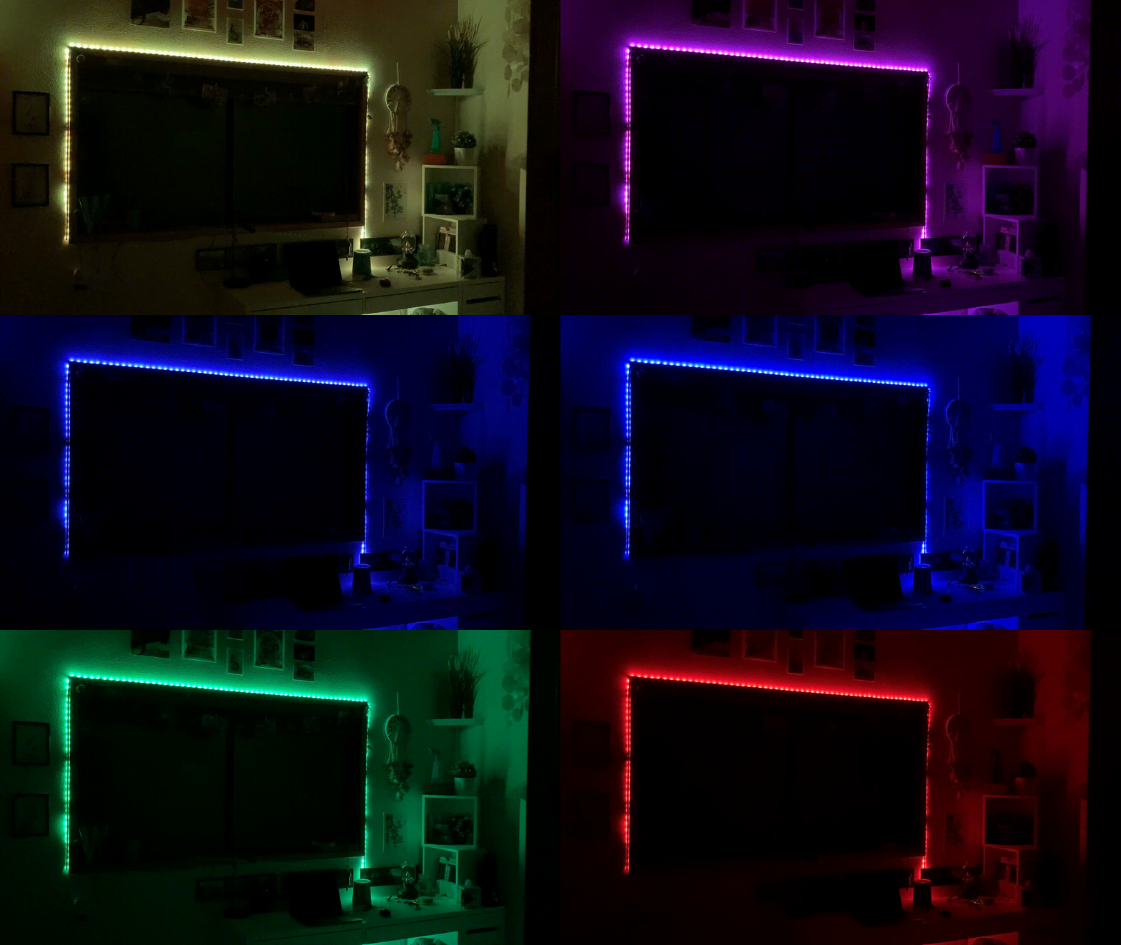
For my final project, I created a product called Party Mode. With party mode, users can create customized color patterns that will cycle on an RGB LED strip. The product allows users to adjust the cycling rate of the RGB LED strip as well as reset color patterns on the fly.
As a culmination of the work I had done with circuits, it was a fun and exciting way to end my quarter with a bang! There's not some higher purpose or deeper meaning behind this project; I had the RGB LED strip and wanted to recreate the infmaous TikTok lights trend.
Demo First! Then Details After
I believe that this project is best explained with a demo to help visualize the entire product in action. Below is my demo video, which can also be viewed on YouTube:
The Circuit
Next, let's dive into the circuitry. Below I have a diagram explaining each of the major components on the breadb—sorry, I mean "prototype."
Note: if any of the diagrams are too small to read and don't like zooming in right click and open the image the in new tab!
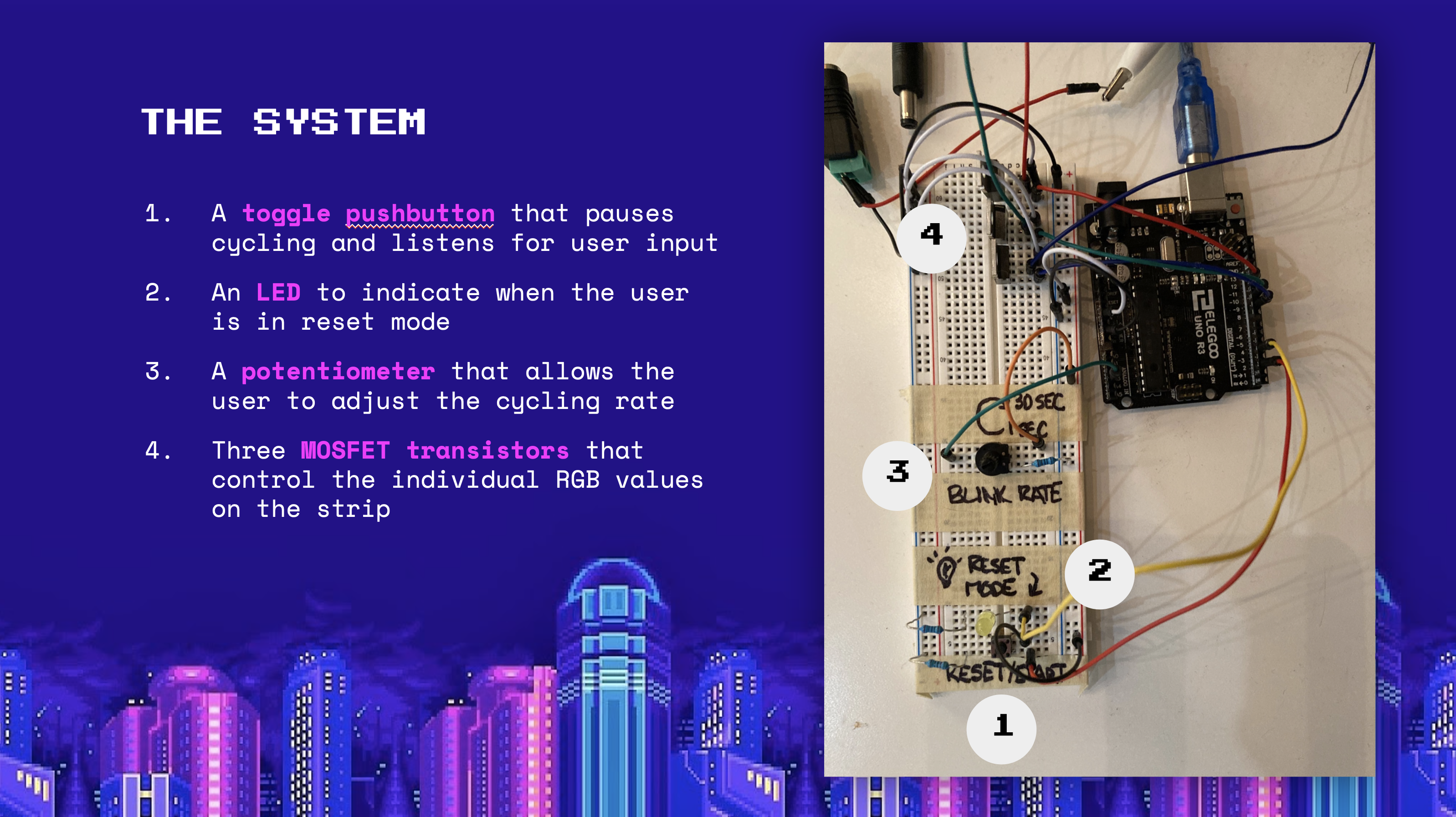
I also have provided a schematic for a more abstract and clearer view of the circuit.The biggest thing to note here is that MOSFET transistors are used to control the RGB LED strip, as we cannot directly manipulate the +12V drain. The Arduino pins then control the transistors' gate, controlling flow similar to a singular RGB LED.
Voltages and Resistances
Before we get to any more of the fun, I have to address the boring aspect of resistances and expected voltages. Here we go!
For resistances:
- The reset pushbutton (#1 on Figure 1) has a an arbitrary 10KΩ resistor to set a low current that wouldn't fry the Arduino.
- The reset LED indicator has a 220Ω resistor becuase it is closest to its ideal resistance of 160Ω after the voltage drop.
- The potentiometer setup has a 1KΩ resistor; this means that the range of resistance for the circuit is 1K–11K.
- The transistors already limit the current flowing through them to a stable range, so no need for resistors here.
For voltages:
- Given the resistance range of 1K–11K for the voltage divider at #3, this gives a more sensitive voltage range of 0.45V–5V.
- The MOSFET transistors are fed a drain of 12V, meaning the range the indivial RGB lines on the strip will see 0-12V.
A Pixel's Journey
Before heading into the code, I think that it's easier to first visualize how the program takes information from the web page and puts it out in the real world.
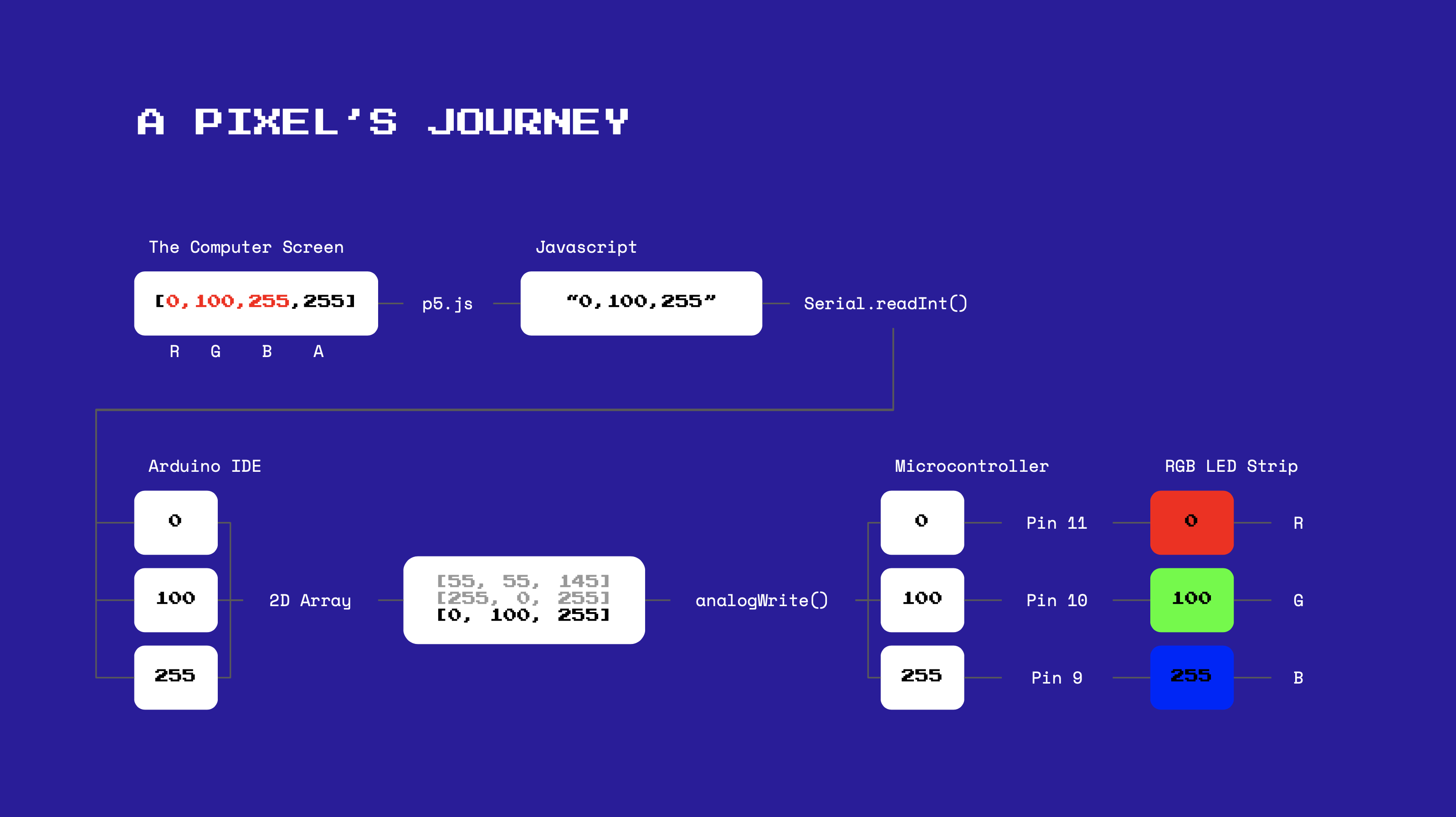
To put it into words, here is what happens. If the mouse is clicked, the program extacts RGB values from the pixel using the cursor's position on the page. The program then sends the RGB values back to Arduino via serial in a comma-separated string. The Arduino reads the integers from the serial and stores them into an array of RGB value arrays. When the color needs to be transmitted, the program writes to the analog pins the RGB values from the array, which manipulate the voltage to produce the color on the RGB LED strip. *Takes a deep breath in* And that is the life of a pixel in Party Mode!
The Javascript Code
There is actually less Javascript code for the final project than the previous prepatory assignment. This is because I removed the joystick feature and solely focused on using the mouse, which cut back much of the code. The main feature here is to grab the pixel's RGBA value from the cursor's position, then send it over the serial.
/*
* Ben Olson
* 03/10/21
* This program send RGB values to the Arduino serial monitor. If the mouse is clicked, the program
* extacts RGB values from the pixel using the cursor's position on the page. The program then
* sends the RGB values back to Arduino via serial.
*/

var serial; // variable to hold an instance of the serialport library
var portName = '/dev/tty.usbmodem142101' // port that is connected to my microcontroller


function setup() {
 serial = new p5.SerialPort();       // make a new instance of the serialport library
 serial.on('list', printList);       // set a callback function for the serialport list event
 serial.on('connected', serverConnected); // callback for connecting to the server
 serial.on('open', portOpen);        // callback for the port opening
 // serial.on('data', serialEvent);     // callback for when new data arrives
 serial.on('error', serialError);    // callback for errors
 serial.on('close', portClose);      // callback for the port closing

 serial.list();                      // list the serial ports
 serial.open(portName);              // open a serial port
 createCanvas(1023, 1023);           // creates a canvas 1023px by 1023px
}

// get the list of ports:
function printList(portList) {
// portList is an array of serial port names
for (var i = 0; i < portList.length; i++) {
// Display the list the console:
  print(i + " " + portList[i]);
}
}

// prints server connection success
function serverConnected() {
 print('connected to server.');
}

// prints the serial port opened
function portOpen() {
 print('the serial port opened.')
}

// prints if there's an error connecting to the serial port
function serialError(err) {
 print('Something went wrong with the serial port. ' + err);
}

// prints that the port is closed
function portClose() {
 print('The serial port closed.');
}

// predefines image variable
let img;

// preloads the image for faster processing when redrawing
function preload() {
 img = loadImage('color-wheel-2.png'); // loads defined image in directory
}

// draws the image once
function draw() {
 image(img, 0, 0, width, height);
 noLoop();
}

// targets pixel based on cursor position when clicked, then extracts RGB values from pixel and sends to Arduino
function mouseClicked() {
 // if the pixel color selected is not white (can omit for images not in full saturation)
 if (get(mouseX, mouseY).toString() != [0,0,0,0].toString()) {

   // grabs pixel from cursor position
   let pixel = get(mouseX, mouseY);

   // writes RGB values from pixel to the serial, values separated by commas
   serial.write(pixel[0] + ',' + pixel[1] + ',' + pixel[2]);

   // logs RGB values to console
   console.log(pixel[0] + '\n' + pixel[1] + '\n' + pixel[2] + '\n');
 }
}
The Arduino Code
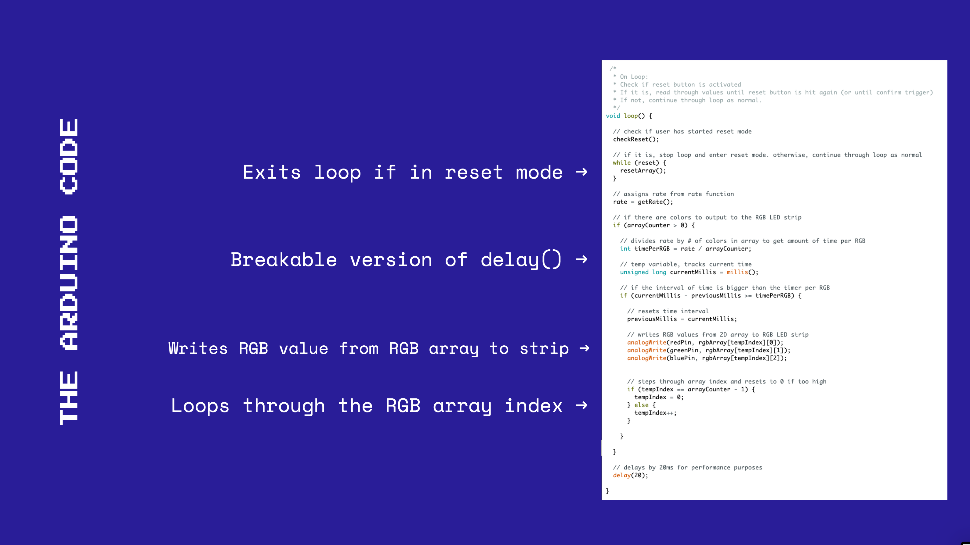
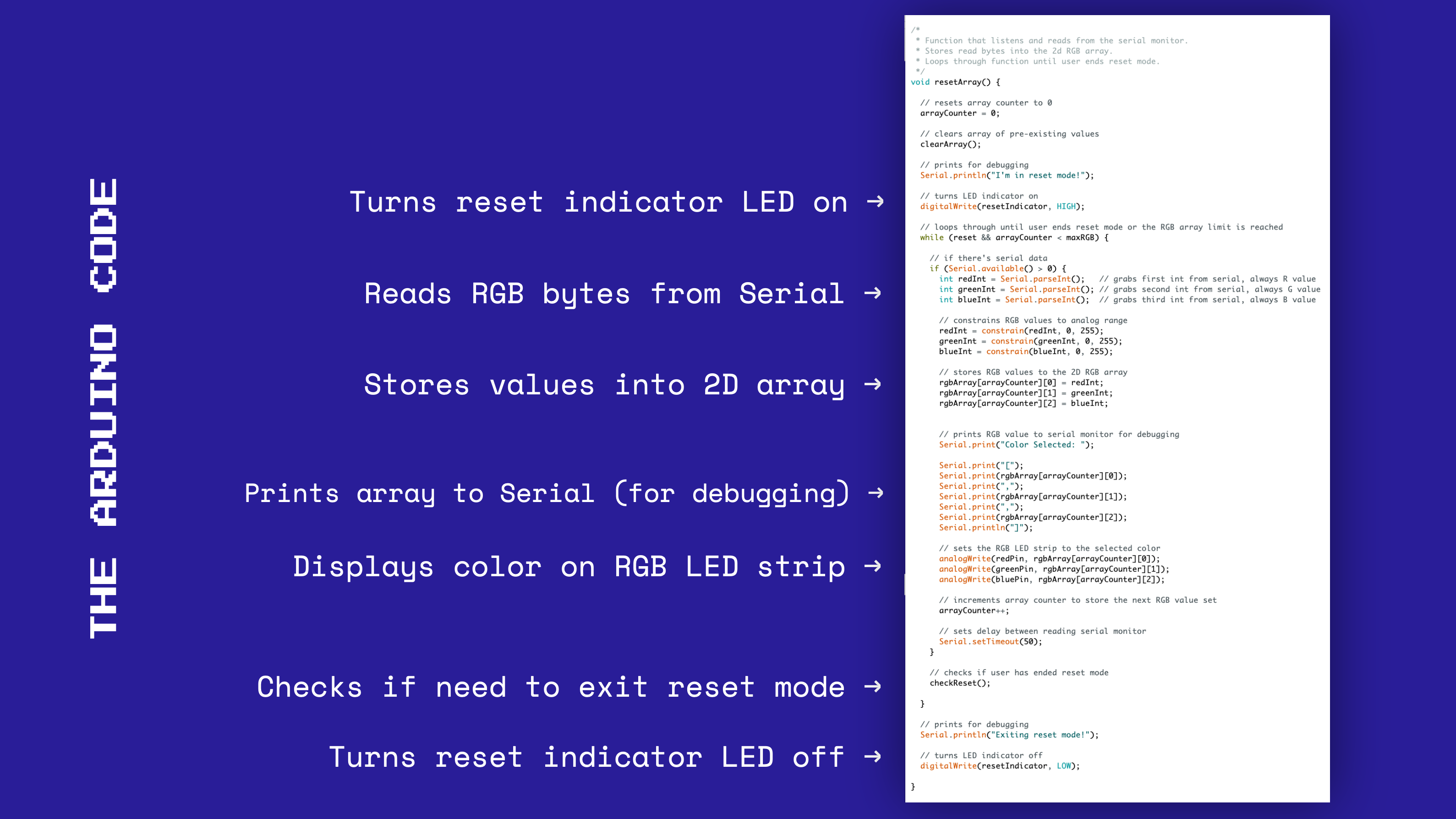
The Arduino code is a bit beefy. To help chunk out what's going on, on top of the raw code I have also provided a couple of annotated diagrams that help explain the two essential functions of the Arduino code: the main loop and the reset loop.
/*
* Ben Olson
* 03/01/21
* This program reads RGB values taken from the web and stores them into an array of RGB value arrays.
* This array then is cycled through, outputting RGB values to an RGB LED strip.
* Potentionmeter analog values determine the rate of cycling between RGB values.
* A reset button allows users to stop cycling and re-map colors from the web.
*/

// initializes pins
const int redPin = 11;    // sets RGB red to 11
const int greenPin = 10;  // sets RGB green to 10
const int bluePin = 9;    // sets RGB blue to 9
const int resetPin = 2;   // sets reset pin to 2
const int resetIndicator = 4; // sets reset indicator pin to 4
const int potPin = A3;    // sets potentiometer pin to A3

// constants
const int maxRGB = 100;   // max array length

// reset debounce variables
int reset = HIGH;         // the current state of the output pin
int resetState;             // the current reading from the input pin
int lastResetState = LOW;   // the previous reading from the input pin
unsigned long lastDebounceTime = 0;  // the last time the output pin was toggled
unsigned long debounceDelay = 20;    // the debounce time


// RGB array variables
int rgbArray[maxRGB][3];    // the 2D RGB array, stores sets of RGB values 3 units long
int arrayCounter;           // size of stored RGB values in RGB array
int tempIndex = 0;          // index to loop through array

int rate;                   // rate calculated from potentiometer

unsigned long previousMillis = 0; // time tracker for main loop

/*
* Initializes serial and pins.
* Begins user in reset mode.
*/
void setup() {

 // initializes serial monitor to 9600 baud
 Serial.begin(9600);


 // sets appropriate pins to output mode
 pinMode(resetPin, INPUT);
 pinMode(redPin, OUTPUT);
 pinMode(greenPin, OUTPUT);
 pinMode(bluePin, OUTPUT);
 pinMode(resetIndicator, OUTPUT);

 // gets initial rate from potentiometer
 rate = getRate();

 // begins user in reset mode
 resetArray();

}

/*
 * On Loop:
 * Check if reset button is activated
 * If it is, read through values until reset button is hit again (or until confirm trigger)
 * If not, continue through loop as normal.
 */
void loop() {

 // check if user has started reset mode
 checkReset();

 // if it is, stop loop and enter reset mode. otherwise, continue through loop as normal
 while (reset) {
   resetArray();
 }

 // assigns rate from rate function
 rate = getRate();

 // if there are colors to output to the RGB LED strip
 if (arrayCounter > 0) {

   // divides rate by # of colors in array to get amount of time per RGB
   int timePerRGB = rate / arrayCounter;

   // temp variable, tracks current time
   unsigned long currentMillis = millis();

   // if the interval of time is bigger than the timer per RGB
   if (currentMillis - previousMillis >= timePerRGB) {

     // resets time interval
     previousMillis = currentMillis;

     // writes RGB values from 2D array to RGB LED strip
     analogWrite(redPin, rgbArray[tempIndex][0]);
     analogWrite(greenPin, rgbArray[tempIndex][1]);
     analogWrite(bluePin, rgbArray[tempIndex][2]);


     // steps through array index and resets to 0 if too high
     if (tempIndex == arrayCounter - 1) {
       tempIndex = 0;
     } else {
       tempIndex++;
     }

   }

 }

 // delays by 20ms for performance purposes
 delay(20);

}

/*
* Function that reads analog value from potentiometer.
* Gets, constrains, maps, and returns processed value from the potentiometer.
*/
int getRate() {
 int input = analogRead(potPin);
 input = constrain(input, 100, 1023);             // sets floor to 100 to limit rate to help users hit low values more
 int result = map(input, 100, 1023, 1000, 30000); // constrains period range to 1s to avoid epilepsy and 30s to stay within int type range
 return result;
}

/*
* Function that listens and reads from the serial monitor.
* Stores read bytes into the 2d RGB array.
* Loops through function until user ends reset mode.
*/
void resetArray() {

 // resets array counter to 0
 arrayCounter = 0;

 // clears array of pre-existing values
 clearArray();

 // prints for debugging
 Serial.println("I'm in reset mode!");

 // turns LED indicator on
 digitalWrite(resetIndicator, HIGH);

 // loops through until user ends reset mode or the RGB array limit is reached
 while (reset && arrayCounter < maxRGB) {

   // if there's serial data
   if (Serial.available() > 0) {
     int redInt = Serial.parseInt();   // grabs first int from serial, always R value
     int greenInt = Serial.parseInt(); // grabs second int from serial, always G value
     int blueInt = Serial.parseInt();  // grabs third int from serial, always B value

     // constrains RGB values to analog range
     redInt = constrain(redInt, 0, 255);
     greenInt = constrain(greenInt, 0, 255);
     blueInt = constrain(blueInt, 0, 255);

     // stores RGB values to the 2D RGB array
     rgbArray[arrayCounter][0] = redInt;
     rgbArray[arrayCounter][1] = greenInt;
     rgbArray[arrayCounter][2] = blueInt;


     // prints RGB value to serial monitor for debugging
     Serial.print("Color Selected: ");

     Serial.print("[");
     Serial.print(rgbArray[arrayCounter][0]);
     Serial.print(",");
     Serial.print(rgbArray[arrayCounter][1]);
     Serial.print(",");
     Serial.print(rgbArray[arrayCounter][2]);
     Serial.println("]");

     // sets the RGB LED strip to the selected color
     analogWrite(redPin, rgbArray[arrayCounter][0]);
     analogWrite(greenPin, rgbArray[arrayCounter][1]);
     analogWrite(bluePin, rgbArray[arrayCounter][2]);

     // increments array counter to store the next RGB value set
     arrayCounter++;

     // sets delay between reading serial monitor
     Serial.setTimeout(50);
   }

   // checks if user has ended reset mode
   checkReset();

 }

 // prints for debugging
 Serial.println("Exiting reset mode!");

 // turns LED indicator off
 digitalWrite(resetIndicator, LOW);

}


/*
* Function that clears the 2D RGB array of pre-existing values.
* Wipes the current color state of the RGB LED strip.
*/
void clearArray() {
 // loops through the part RGB array that has values stored
 for( int i = 0; i < maxRGB;  i++ ) {

   // sets RGB array at index to 0
   rgbArray[i][0] = 0;
   rgbArray[i][1] = 0;
   rgbArray[i][2] = 0;

 }

 // shuts off the RGB LED strip from any interrupted color
 analogWrite(redPin, 0);
 analogWrite(greenPin, 0);
 analogWrite(bluePin, 0);
}


/*
* Function that checks if the user has started/ended reset mode.
* Listens for change in value from pushbutton after debounce delay.
* Sets global reset variable depending if switch is toggled on or off
*/
void checkReset() {
 // read the value of the reset button
 int reading = digitalRead(resetPin);

 // if the button value changed from last reading
 if (reading != lastResetState) {
   // reset the debouncing timer
   lastDebounceTime = millis();
 }

 // if the time interval is longer than the preset debounce delay
 if ((millis() - lastDebounceTime) > debounceDelay) {

   // if the button state has changed:
   if (reading != resetState) {

     // sets the reset state to the current reading
     resetState = reading;

     // only toggle the global reset variable if the new reset state is HIGH
     if (resetState == HIGH) {
       reset = !reset;
     }
   }
 }

 // save the reset state
 lastResetState = reading;
}
Problems with the Arduino Code
I think that one of the biggest issues I had with the Arduino code concerned the main loop and how to run code asynchronously from that very limiting span.
The reset process I had in mind required me to break the main loop, so my solution was to create a separate function and code in a while loop that would run indefinitely until either the user ends the reset process or the max array limit is reached. I don't know if this is quality coding, but it got the results I wanted.
My second qualm with the main loop was that I could only go into reset mode or apply a different cycling rate one every couple of seconds, and not instantaneously. This is becuase my delays set by the potentiometer-controlled rate would not allow for any input to interrupt the code. To solve this, I used some fancy code using millis() to keep track of time. For every pass through the function, it checks if a certain amount of time has passed before executing. This allowed me to interrupt the loop as any given moment as well as have the cycling rate run asynchronous to the loop clock.
When The Party's Over
Overall, this project has been such a blast for me. It was really cool to take something accidentally given to me (the RGB LED strip was a packaging mistake) and give it meaning and charm through hard work and lots of code. I know I've said this a lot now, but I am genuinely so proud of the work I have accomplished here in this class. It's refreshing to be tinkering with my hands, and it brings back joys of playing with LEGOs as a kid.
Anyways, enough sentimental talk. I hope that you enjoyed reading my project! If you have been sticking around, I am glad (and surprised) that you've seen me grow as a circuiter (probably not a word) and engineer over these past 10 weeks. Now, it's time to retire the breadboard and microcontroller for now. Until next time, party on!